LED Block Game
Mouser Electronics Technical Support Team
Licensed under CC BY-SA 4.0
Software
Wireless Controller Software
Program the controller software by using the PICkit 3 in-circuit Debugger, Microchip MPLABX, and XC8 Compiler. Find the necessary files in the GameController.zip file, and then unzip and import them as a project into MPLAB X.
We recommend that you use a daughter card (such as the Microchip PICkit 3 Low Pin Count Board, Mouser part # 579-DM164130-9) for programming the PIC16, but you can also use simply a breadboard and header pins. The following image shows the correct pinout of the target and PICkit debugger.
 Pinouts of PICkit 3 board.
Display Software
The software installation for the chipKIT Max32 used to drive the LED display require the Arduino integrated development environment (IDE) and chipKIT board manager libraries.
To download the Arduino IDE, go to https://www.arduino.cc/en/Main/Software.
After installing and opening the Arduino IDE follow these steps to add the chipKIT board manager libraries.
- In the Arduino IDE, click File, and then click Preferences.
- In the Preferences dialog box, locate the Additional Boards Manager URLs: field.
a. If the field is blank, paste the following URL, and then click OK: https://github.com/chipKIT32/chipKIT-core/raw/master/package_chipkit_index.json.
b. If there is already a URL in the field, click the box icon to the right of the text field to open a dialog box, paste the following URL, and then click OK: https://github.com/chipKIT32/chipKIT-core/raw/master/package_chipkit_index.json.
- Click OK to close the Preferences dialog box.
- Click Tools, select Board, and then click Boards Manager.
- In the Boards Manager dialog box, scroll down to the entry for the chipKIT board, and then click anywhere in the entry to bring up the Install button. Click the Install button.
- Once the installation is complete, click Close.
- Click Tools, select Board, and then click chipKIT MAX32.
After adding the chipKIT to the Boards Manager but before verifying or uploading your software (called a "sketch"), use the following steps to add the PICxel library:
- Click Sketch, select Include Library, and then click Add .ZIP Library….
- Browse to the location of your .ZIP file, select the PICxel.h file, and then click Open.
- #include <PICxel.h> appears in your sketch.
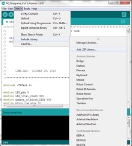 Selecting a library in the Arduino IDE.
Now that you have the IDE, Boards Manager, and libraries installed, you can begin loading the sketch onto the chipKIT. Connect the board to the computer using a Mini USB-to-USB A cable and wait for the automatic driver installation. Once the drivers are installation, ensure you have selected the correct board and serial port for communication.
Click Tools, select Ports, and then choose the correct port.
In the following image, we've selected the chipKIT MAX32 board and the COM41 serial port, but your port may be different:
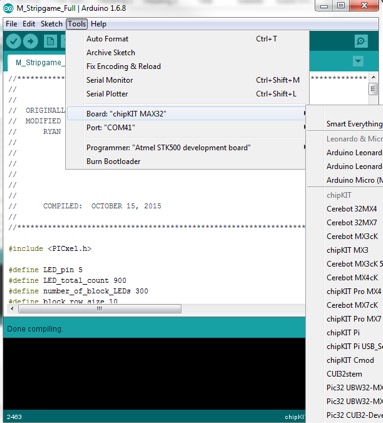 Selecting a board and COM port in the Arduino IDE.
To load the sketch onto the chipKIT, click the arrow (Upload) button, and wait for the message "Done compiling."
XBee Programming
For ease of programming, we have provided the transmitter (wireless controller) and receiver (chipKIT) profile files, which you upload to the XBee modules using the XCTU software. For the wireless controller, use the Transmit_XBEE file; for the chipKIT, use the Receive_XBEE file. Use the XBee-to-USB adapter to interface and program the modules. When plugging the XBee module into the adapter, align pin 1 on the module with pin 1 of the adapter.
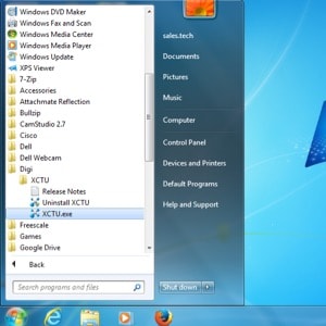 Launching the XCTU software.
On your computer, find and launch the XCTU software. In the XTCU window, click the Discover Device icon to detect the XBee modules connected to the system.
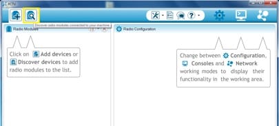 Detecting XBee modules in XCTU.
Plug the XBee-to-USB adapter into your computer using a Mini-USB cable. Once the driver installation is complete, click the Discover Device icon. If multiple COM ports are displayed, select the one listed as USB Serial Port.
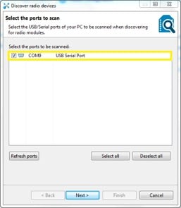 Select the correct COM port.
Click Next to launch the Set port parameters dialog box. You do not need to change any parameters, so click Finish to close the dialog box.
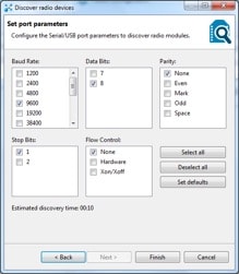 Reviewing the port parameters.
Once the selected device is found, a window will display relevant information such as port configurations and MAC address. Click Add selected devices.
 Adding the XBee device to selected devices.
The connected XBee module appears on the home screen under Radio Modules.
 Connected radio modules.
Select the Radio Module to load and list the device's default or configured parameters.
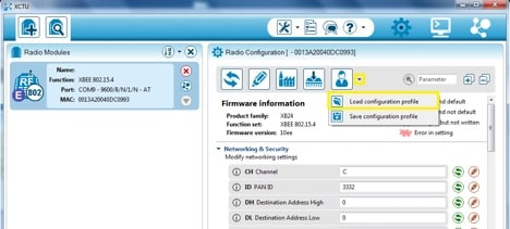 Loading the configuration profile.
Click the Profile icon and select Load configuration profile. Browse to and select either the Receive or Transmit file, depending on which device you are programming.
Changes to the profile will appear as either a highlighted green box or a green arrow to the right.
Click the Write radio settings icon. When you receive confirmation that the programming is complete, unplug the configured XBee module. Repeat this procedure to configure the second module.
We would love to hear what you think about this project; please tell us in the comments section below.


