iRoboBumper: SONAR-Obstacle Detection System for Robotics Platforms
Licensed under CC BY-SA 4.0
System Overview
Ultrasonic sensors operate on the "time of
flight" principal to determine distance. One example is the PING)))TM Ultrasonic Distance Sensor, made by Parallax Inc. This sensor module
has all of the circuitry needed to emit 40 kHz sound waves and listen for the echoes (i.e. reflected pulses). It
outputs a 5-V Transistor-Transistor Logic (TTL) signal, which has a high duration that can be used to
determine the range to the object that reflected the pulses of sound. The range of the PING))) sensor extends
out to approximately 3 meters, but varies based on the reflectivity of the obstacle. Figure 1 shows a depiction
of the PING))) sensor and interface.
Figure 1: PING))) Sensor and interface. By measuring the echo
pulse width, the distance to the target can be easily calculated. (Source: PING))) Sensor
Guide)
The PING))) sensor has a field of view (FOV) of roughly 40 degrees (+/- 20 degrees from the direction it is
facing) and is capable of 50 readings per second. Since we want a full 360 degree FOV and most ground based
hobby robotic platforms do not need a 50Hz update rate, we can pan the PING))) sensor while continuously taking
measurements to tradeoff a slower sampling rate at a given angle for increased FOV. Thus, the equations for
these tradeoffs are as follows:
Same Angle Update Rate (Hz) = Pan Rate (degrees/sec) / 360 (degrees)
Sample Spacing (degrees) = Pan Rate (degrees/sec) / 50 (samples/sec)
For example, if we pan the PING)))TM sensor 360 degrees every 2 seconds this gives use a pan rate of 180 degrees
per second. From the above equations, we get a Same Angle Update Rate of 0.5 Hz and a Sample Spacing of 3.6
degrees. This means, given a stationary base, we will sample the same object every 2 seconds and that the system
pans 3.6 degrees between readings.
However, if we pan 360 degrees every second we obtain a same angle update rate of 1 Hz and a sample spacing of
7.2 degrees. This is a tradeoff between angular resolution and update rate. However, we could utilize multiple
PING)))TM sensors pointed in opposite directions to effectively double (2 sensors), triple (3 sensors), or more
the Same Angle Update Rate at a given pan rate. For this project, two PING)))TM sensors facing in opposite
directions will be used to double the Same Angle Update Rate. In addition, we will also aim for a continuous pan
rate in the 180-360 degrees per second range. The distance to an obstacle from the PING)))TM sensor is
calculated by multiplying the duration that the PING)))TM sensor drives the signal high by the speed of sound in
air that is measurable by the sensor. The datasheet for the sensor gives the speed of sound in air as:
Cair = 331.5 + (0.6 * TC) meters/sec
Where TC is the temperature in degrees Celsius of the air. This temperature component can account for
up to a 12 percent error over the 0 to 70 degree Celsius operating range of the sensor. In order to minimize
this, a temperature sensor will be added to the system and used to calculate the speed of sound in air per the
equation above. A Texas Instruments LMT87 temperature sensor (Figure 2) was selected as it can operate off the
same 5-V supply needed by the PING)))TM sensor and it has a single analog output that varies almost linearly
with respect to its temperature.
Figure 2: Texas Instruments LMT87LP
To allow continuous panning of the sensors, a motor is required. For this project, a hobbyist servo, configured
for continuous spin operation, will be used. The servo selected is Parallax
Inc.'s Standard Servo (Part Num. #619-900-0005), which is pictured in Figure 3. After researching this
servo, it is just a Futaba S148 servo which has been configured for continuous movement. Being a standard servo
configured for continuous spinning, the input signal is used to control the speed and direction of the servo by
varying the duty cycle of the Pulse Width Modulated (PWM) signal. This servo is specified to run up to 6.0 V;
however, several of Parallax’s example applications drive this servo off of 4x AA batteries. The nominal voltage
of a single AA battery is 1.5 V, meaning four of them in series would be 6 V. However, new AA batteries can
easily have a voltage in the 1.7 V range. Given Parallax’s examples though, we are led to believe that powering
the servo with 4x AA batteries should work fine.
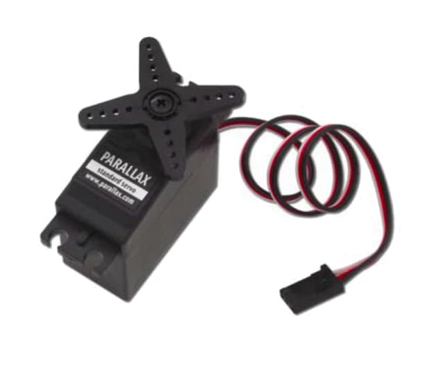
Figure 3: Parallax Standard Continuous Spin Servo
Spinning the two PING))) sensors using the continuous servo introduces a few complications to the design. Servos
normally use a potentiometer to repeatedly return to a position based on the PWM control signal. However, in a
servo configured for continuous rotation this is disabled and the PWM signal is used to control the speed and
direction of the servo. So, we have a servo that we can speed up or slow down and change direction.
Unfortunately, we do not have a way to determine the exact pan rate (degrees / second) that the servo is
spinning and no way of knowing what direction the PING))) sensors are facing relative to the non-rotating base
of the system that is fixed to the host robotics platform.
To overcome both of these issues, we will use a proximity sensor to detect alignment holes that will be placed in
the non-rotating base of our system. The position of these alignment holes will allow our system to identify the
“home” position without needing to know what direction the PING))) sensors are facing when powering up. Since
the orientation of the non-rotating base of our system relative to the host robotics platform does not change,
this home position will be consistent relative to the host robotics platform as well. In addition, the time it
takes to pass these fixed alignment holes will be used to determine the current pan rate of the system and
change the PWM control signal of the servo to maintain the desired pan rate.
The proximity sensor that was chosen is a Vishay TCRT1010
and is shown in Figure 4. This is a reflective optical sensor that consists of a near-IR (i.e. 950nm) LED and
phototransistor integrated into a single package. The amount of current that flows through the phototransistor
changes based on the amount of near-IR energy that it is receiving. In principal this means that as an object
approaches the device, more IR energy from the LED is reflected back to the phototransistor which causes more
current to flow from the collector to the emitter. The detection distance for this device is short (i.e. in the
2-15mm range), but is adequate for detecting alignment holes in the base.
Figure 4: Vishay TCRT1010 Proximity Sensor
The final complication from using a continuously spinning servo is the fact that it makes connecting
communications and power interfaces to the host robotic platform difficult. Most systems with this type of
configuration would use what is called a slip ring to
pass signal and power through a rotating axis. However, this can be expensive and problematic.
Instead of a slip ring, we will host our power source (i.e. 4 AA batteries) within the rotating part of the
system and use a wireless link to the host robotics platform. It is desired to keep the interface for the
wireless communication as simple as possible. For this reason and the fact that it allows for the use of
different wireless protocols, a DIGI XBee communication module was chosen. This allows the
interface on both sides to be a simple 2-wire UART (i.e. TX and RX) and the XBee modules act as a wireless
serial adapter. Typical XBee modules (i.e. ZigBee and WiFi based) are pictured in Figure 5:
Figure 5: DIGI XBee
Modules (ZigBee on left, WiFi on right)
The final major component of the system is the microcontroller. After considering the mix of interfaces that need
to be handled (i.e. PWM, Analog to Digital Conversion, Serial Port, and external interrupts) and the voltage
levels of each (i.e. mostly 5-V logic), an Arduino Pro
Mini 16Mhz / 5-V module was selected. This board has all of the IO requirements for the selected
components and is relatively small in size. Figure 6 depicts the Arduino Pro Mini that was selected. (At
slightly more cost, the Nano will also work and has more
amenities.)
Figure 6: Gravitech Arduino Pro Mini 5 Volt.
We would love to hear what you think about this project; please tell us in the
comments section below.


